Forming Bézier curves in OpenSCAD
Higher level polygons
While Bézier curves are invaluable for art and animation — with uses ranging from SVGs to CSS transitions — could we really make use of them in OpenSCAD? I had my doubts, since I was unable to do other — seemingly simple tasks, like building up a column by stacking a series of cones and cylinders.
That project failed because I was unable to express a sum function which would add up all the values of a vector into a single scalar. (More on that in a future post.) Today’s question is, Isn’t the math involved with Bézier curves much more complicated than adding? Won’t this fail, too?
Only one way to find out! First, I needed to understand what Bézier curves are, exactly. For that, I used Pomax’s Primer on Bézier Curves to help me get up to speed. This article oscillates between oversimplifying and then precisely describing the math involved. If you find yourself confused by the simplistic explanations, my advice is to read faster, and don’t ask too many questions until you get to the “juicy” parts.
Overall, it’probably a great primer, likely at multiple levels of understanding. It helped me understand that all I needed was a specific formula for cubic Bézier curves, and then it conveniently provided it under Controlling Bézier curvatures.
Here’s that formula:
$$ \begin{matrix} x &= w_{x_0}(1 - t)^3 + 3tw_{x_1}(1 - t)^2 + 3t^2w_{x_2}(1 - t) + t^3w_{x_3} \\ y &= w_{y_0}(1 - t)^3 + 3tw_{y_1}(1 - t)^2 + 3t^2w_{y_2}(1 - t) + t^3w_{y_3} \\ \end{matrix} $$
Basically, we have four points that define the position of the curve,
$$ \begin{matrix} p_1 &= (w_{x_0}, w_{y_0}), & p_2 &= (w_{x_1}, w_{y_1}) \\ p_3 &= (w_{x_2}, w_{y_2}), & p_4 &= (w_{x_3}, w_{y_3}) \end{matrix} $$
and the entire curve must exist within the bounding box of these four points. Additionally, the curve starts at point \(p_0\) and ends at \(p_4\), with the influence of each of the four points varying over the length of the curve, which is traced by \(t\). (\(t\) doesn’t limit the size of the curve at all; rather, these functions are normalized so that as \(t\) goes from 0 to 1, the output values go from the starting point to the ending point.)
Now, rather than diving deeper into a mathematical explanation, let’s just see the code.
module bezier(start, one, two, end, resolution=100) {
The module receives four points and a resolution parameter. The resolution is the number of lines to draw between start and end; The total number of vertices is \(\text{resolution} + 1\). Unfortunately, OpenSCAD does not allow us to include an accented character (é) in our module name.
Next, we build a vector of points by taking \(\text{resolution} + 1\) steps from zero to one — inside a for loop inside a vector generator expression.
  points = [
    for (t = [0 : 1/resolution : 1]) [
        ...
    ]
  ];
Inside the for loop, we just calculate each point as a 2-vector.
    [
      start.x * (1 - t)^3
        + 3*t*one.x * (1-t)^2
        + 3*(t^2)*two.x*(1-t)
        + (t^3)*end.x,
      start.y * (1 - t)^3
        + 3*t*one.y * (1-t)^2
        + 3*(t^2)*two.y*(1-t)
        + (t^3)*end.y
    ]
Apparently, there’s a way to use let in OpenSCAD to allow us to simplify the way this looks — for example we could assign \(1 - t\) to a variable to save some space — but I’m too scared to try it. Variable assignment in OpenSCAD is weird, and it defies all of my expectations as a programmer.
Once we have our points defined, we just render them as a polygon.
polygon(points);
polygon will connect the start and end point with a line to make a closed shape. That’s really all there is to it!
module bezier(start, one, two, end, resolution=100) {
  points = [
    for (t = [0 : 1/resolution : 1]) [
      start.x * (1 - t)^3
        + 3*t*one.x * (1-t)^2
        + 3*(t^2)*two.x*(1-t)
        + (t^3)*end.x,
      start.y * (1 - t)^3
        + 3*t*one.y * (1-t)^2
        + 3*(t^2)*two.y*(1-t)
        + (t^3)*end.y
    ]
  ];

  //echo("bezier", points=points);

  polygon(points);
}
You can use the module like so:
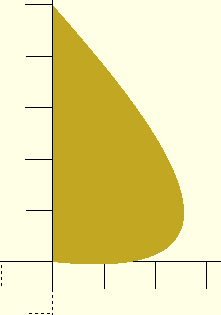
bezier([0,5], [1.75, 3], [4.75, -0.5], [0, 0]);

You can see how easily I’ve created a complex shape which can be used as a detent mechanism to hold two 3d-printed parts together. All this from four, carefully selected numbers.
Now, there’s a little song and dance needed to integrate this Bézier shape into your typical modelling application. You see, it’s very important to know the dimensions of this shape; but the four control points only define the maximum possible dimensions.
Also, it’s important to be able to scale the detent to an exact size defined by its application, without changing its basic shape.
We can accommodate both of these with a little grunt work. First, we have the bezier module print out all of its points with this echo statement.
echo("bezier", points=points);
Then, we manually review the output to find the bounding box of the shape. For my application (making a detent), I felt that knowing the exact width of the shape was enough, so I identified the maximum x value and used that as a scaling factor in my detent module.
In this case, that scaling factor is 2.556, which I denoted as natural_thickness, below.
module cyl_detent(cylinder_radius, detent_clearance, detent_thickness, resolution=100) {
  outer_radius = detent_thickness + cylinder_radius;

  // The bézier was measured without any scaling to have a maximum thickness of exactly this amount.
  natural_thickness = 2.556;

  translate([0, 0, detent_clearance])
    toroid(cylinder_radius, resolution)
    scale(detent_thickness/natural_thickness)
    bezier([0,5], [1.75, 3], [4.75, -0.5], [0, 0], 100);

}
(The missing toroid module is merely a wrapper around rotate_extrude, which tames it a little bit and allows changing the resolution easily.)
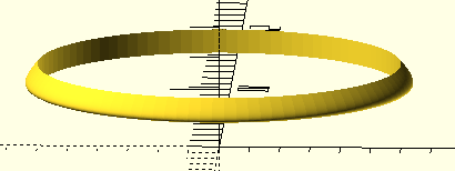
As an example, the following code outputs a toroidal ring with the shape of the Bézier curve traced around the outside. The interior is hollowed out, and designed to be attached to a cylinder with a radius of cylinder_radius. Additionally, it’s raised above the origin by detent_clearance, which is the clearance needed for whatever item is supposed to be secured by the detent.
cyl_detent(3, 2, 0.4);

Basically, this allows you to attach a detent to a post and holds some item in place against the post. It’s missing the “stop” opposite the detent which holds the item flush against the back of the detent; but for some applications that stop may not even be part of the post, so to include it here it would reduce the number of useful applications of this module. Just imagine that the ground is the stop.