Approximating a cylinder in OpenSCAD
Approaching the limit with sanity
When you create a circle in OpenSCAD, it has a fixed resolution — or in other words, a fixed number of straight-edged sides to approximate an ideal circle. For example, the following code renders a polygon with about 16 sides.
circle(5);
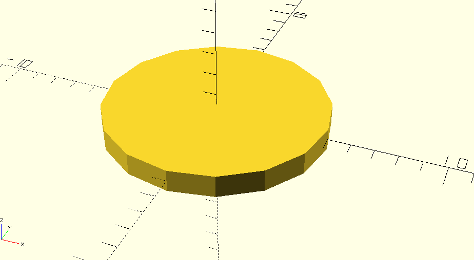
ChatGPT calls that a hexadecagon. The resolution is good! However,
circle(1);
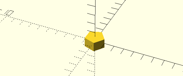
renders a pentagon! What went wrong? Well, it appears that OpenSCAD’s circle module renders a polygon with a specific side length, rather than a specific number of sides.
When we need a closer approximation of a circle, one of the official recommendations from the documentation is to scale the circle like so:
circ(1);

module circ(r, resolution=100) {
  scale(1/resolution)
    circle(r=r*resolution);
}
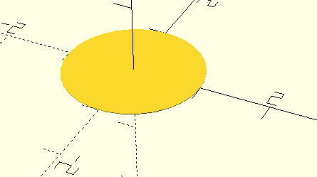
This creates a circle with a large diameter relative to the circle module’s pre-set side-length and then scales down the result to the correct, final size. You’ll note that the rendered height is also scaled down. This is an artifact of how the renderer gives a bit of thickness to 2D shapes; it doesn’t affect how the shape can be used.
Now, using a “resolution” of 100 doesn’t increase the granularity by exactly 100, because the side length is not one.
Okay, so how about for a cylinder? Does this work?
union() {
    cyl_bad(h=1, r1=9, r2=9, resolution=100);
    cyl_bad(h=2, r1=8, r2=8, resolution=50);
    cyl_bad(h=3, r1=7, r2=7, resolution=50);
    cyl_bad(h=4, r1=1, r2=1, resolution=100);
}

module cyl_bad(h, r1, r2, resolution=100) {
  scale(1/resolution)
    cylinder(h * resolution, r1 * resolution, r2 * resolution);
}
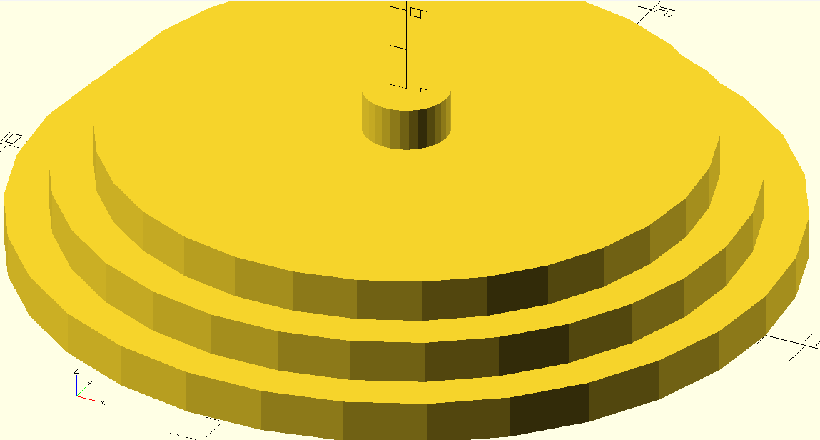
It does not! This time, the radius of the cylinder has no influence over the on the number of sides. It appears to use the same number of sides regardless of the radius of the cylinder. While it’s a shame that it’s inconsistent, this is honestly a better default than the behavior of the circle module. Look how decent the radius-one cylinder looks!
Anyway, you can correct that flaw using the $fa hidden parameter, which is also available as an alternative solution for circles.
cyl(h=1, r1=9, r2=9, resolution=100);

module cyl(h, r1, r2, resolution=100) {
  scale(1/resolution)
    cylinder(h * resolution, r1 * resolution, r2 * resolution, $fa=(360/resolution));
}
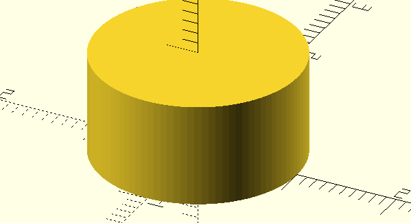
$fa determines how many sides to use when approximating the cylinder’s circumference.
If you want to get really nerdy, though, you can create your own high-resolution cylinder module — and I do!
module cyl_res(h, r, resolution=100) {
First, some set-up. We want to approximate a circle with a series of equal-length chords. This means that the polygon we create will fit inside the ideal circle with its points tangent to the circle — rather than having the center of the line segments be tangent to the circle, for instance.
Also, we want to fill in the center of the circle and give it a height, so that it’s a cylinder. We can accomplish all of this by tracing a series of rectangular “beams” that extend out from the center of the circle and which sweep around 360 degrees.
Let’s go through this line by line.
theta = 360/resolution;
Since the resolution parameter equals the number of chords we want to use, each chord will cover an arc defined by the angle theta (\(\theta\)).
  tau = theta / 2;
  chord_length = 2 * r * sin(tau);
Now we can fix the chord position by imagining two radii extending outward to its endpoints. These radii have an angle of \(\theta\) between them. Now, if we bisect the chord with a line going through the center of the circle, we have defined a right triangle which can be used to find the lengths \(c\) and \(h\).
The angle between the bisecting line and either of the radii is half of \(\theta\). Let’s call it tau (\(\tau\)). The radius is the hypotenuse of the triangle, and the length of half of the chord (\(0.5c\)) is \( r * \sin(\tau) \). This works because \(\sin = \frac{Opposite}{Hypotenuse}\) and, since \(r\) is the hypotenuse, \(\cancel{Hypotenuse} * \frac{Opposite}{\cancel{Hypotenuse}}\).
And, of course, chord_length is double that, yielding
$$ \text{chord_length} = 2r * \sin(\tau) $$
  is_odd = resolution%2;
  beam_factor = is_odd ? 1 : 2;
  beam_trans_factor = is_odd ? 0 : 1;
  limit = is_odd ? theta : tau;
We chose to implement an optimization that only works when there’s an even number of chords. These are all the variables that vary based on that. Since they have no meaning on their own, we’ll cover them where they’re used.
beam_length = beam_factor * r * cos(tau);
Similarly to the chord_length, the beam length \(h\) can be defined in terms of that same right triangle. This time we use \(\cos\) to find the length
$$ \text{beam_length} = r * \cos(\tau) = \cancel{r} * \frac{Adjacent}{\cancel{Hypotenuse}} $$
Now for even numbers, we’ll make the beam twice as long, so that we can define the chords on opposing sides of the circle simultaneously.
Now, we’re ready to render our shape. Instead of going line-by-line, let’s unravel it from the inside, out.
cube([chord_length, beam_length, h]);
Here, we define a beam whose length is beam_length, and whose width is chord_length.
        translate([chord_length, beam_trans_factor*beam_length, h]*-0.5)
          cube(...);
When OpenSCAD renders a cube, one of its corners is at the origin; but we need to move it along every axis.
The “short” edge of the beam needs to go in the exact location of the chord, so it moves by half a chord length; and the long edge needs to bisect the origin of the circle for an even resolution — or to not move at all for an odd resolution. That’s why the beam_trans_factor is either 0 or 1.
Additionally, we’ve decided that the cylinder we’re creating will be centered in the vertical direction as well, so we move it along the Z-axis by half its height.
    for (i = [0: theta : limit * resolution]) {
      rotate([0,0,i])
        ...
    }
  }
Now, we need to create multiple beams and sweep them along the radius of the circle. We start at 0, and increment the angle i by \(\theta\) degrees every time, rotating each beam into position about the Z-axis.
And, we keep sweeping ’round until we hit the limit, which is either 180 or 360.
For an even resolution, we only need to sweep half the circle; so we multiply \(\tau\) by the resolution to get 180. For an odd resolution, we must sweep around the whole circle; so we multiply by \(\theta\), yielding 360.
I could have hard-coded limit = is_odd ? 360 : 180, but articulating it in terms of tau or theta is very useful for testing, where you may want to generate a partial shape with
for (i = [0: theta : limit * 3]) {
which renders 3 beams out of the total count.
  union () {
    ...
  }
}
Finally, we union the whole thing together as one shape. In my experience with OpenSCAD, union seems to be implicit when you have multiple supposedly-unrelated shapes rendered together; but it never hurts to be explicit.
Now, let’s use it!
cyl_res(h=1, r=1, resolution=100);
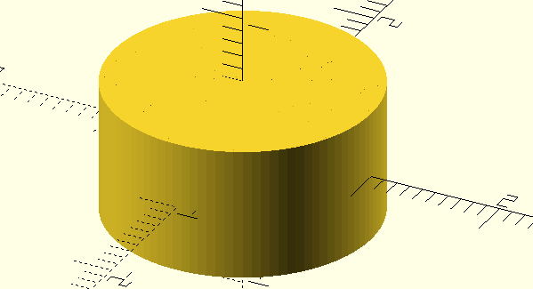
Here’s the entire cyl_res module. Also, all of the models described in this post are available in this supplemental OpenSCAD file.
module cyl_res(h, r, resolution=100) {

  theta = 360/resolution;
  tau = theta / 2;
  chord_length = 2 * r * sin(tau);

  is_odd = resolution%2;
  beam_factor = is_odd ? 1 : 2;
  beam_trans_factor = is_odd ? 0 : 1;
  limit = 	is_odd ? theta : tau;

  beam_length = beam_factor * r * cos(tau);

  echo(r=r, res=resolution, is_odd=is_odd, beam_factor=beam_factor, limit=limit);
  echo(theta=theta, tau=tau, chord_length=chord_length, beam_length=beam_length);

  union () {
    for (i = [0: theta : limit * resolution]) {
      rotate([0,0,i])
        translate([
            chord_length,
            beam_trans_factor*beam_length,
            h]*-0.5)
        cube([chord_length, beam_length, h]);

    }
  }
}